松原Jianan Machinery Sawtooth Wave Jigger Instruction Manual
Product Name: 松原Jianan Machinery Sawtooth Wave Jigger Instruction Manual
Category:松原Sawtooth Wave Jig
Product Overview:
1. Overview
Jigging is one of the main methods of gravity separation.The working principle of jigger is based on gravity beneficiation, using the specific gravity difference between ore and veinstone for sorting, different specific gravity of mineral raw materials in the vertical alternating currents with different settling speeds, larger specific gravity minerals settle faster, occupying the lower part of the sorting tank of jigger, smaller specific gravity minerals settle slower, occupying the upper part of the sorting tank, and through the special weir plate will be different minerals discharged separately to achieve the effect of sorting byThe special weir plate discharges different minerals separately, realising the effect of sorting according to specific gravity.
Sawtooth wave jigger is a kind of high efficient and energy-saving re-election equipment successfully developed on the basis of traditional sinusoidal wave jigger, and the difference between traditional sinusoidal wave jigger and sawtooth wave jigger lies in the following: the pulsating curve of water flow of sawtooth wave jigger is a sawtooth wave, and its ascending water flow is fast, and descending water flow is slow, and the bed layer rises, loosens, and then slowly settles under the action of the ascending water flow, with a long effective time, which can greatly save the amount of rechargeable water under the sieve and greatly reduce the recovery lower part of particle size, which is the best way of separating minerals by specific gravity.Greatly reduce the lower limit of recovery of particle size.After comparing with sine wave jigger, the recovery rate of its operation is higher than that of sine wave jigger by Sn:3.01% and W:5.5% respectively, and the water consumption is reduced by 30~40%.
2. Scope of application
Sawtooth wave jigging beneficiation, because of its simple operation, large processing capacity, in addition to very fine materials, can handle almost all kinds of particle size of mineral raw materials, and can get a certain product in one sorting, so it is widely used in the production of separation of gold, tin, tungsten, tantalum and niobium, titanium, zirconium, chromium primary ores and alluvial ores, and successfully applied in the separation of galena, sphalerite, antimony ore, rhodochrosite, fluorspar and so on, and also is theIt is also one of the main methods for separating diamond and barite, and can be used for separating lead-zinc oxide ores to obtain good results as well.
The greater the difference in density of the minerals to be separated in the ore, the wider the range of particle size can be selected.For gold-bearing alluvial ores, when the feed size is less than 15mm, it can not be classified into the selection, which not only effectively improves the index of sorting but also increases the processing capacity of the equipment.
3. Structure and specification
The structure diagram of newly developed sawtooth wave jigger may not be included in this manual.
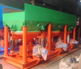
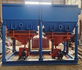
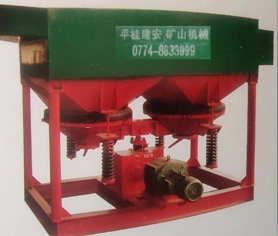
Structure
The structure of sawtooth wave jigger is shown in Fig. 1, Fig. 2, Fig. 3 and Fig. 4.
Type
Sawtooth wave jigger is divided into two types according to the installation position of the drive motor: left and right type.Standing at the end of the feed chute and looking towards the discharge end, the motor on the left is the left type, and the motor on the right is the right type.
Model
The model of sawtooth wave jigger is composed of the pinyin abbreviation of sawtooth wave jigger, the area of jigging chamber, the number of chambers, and the number of driving mechanism, etc. Its model is described as follows:

norm
The specifications and models of sawtooth wave jigger are shown in Table 1.


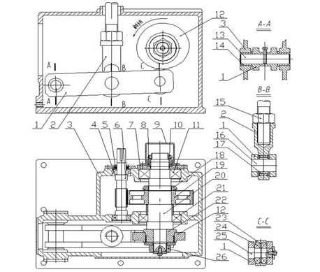
1.Lever 2.Punch block 3.Box 4.Bearing 30206 5.Oil seal 50x30x10
6.High speed gear shaft 7.Bearing gland 8.Bearing 51112 9.Dust cover 10.Round nut
11.Bearing 6313 12.Cam 13.Long shaft 14.Bushing 15.Nut 16.Centre shaft
17.Joint bearing UC45 18.Round nut 19.Large gear 20.Eccentric shaft 21.Bearing NU216
22.Angle adjusting gear 23.Roller 24.Bearing 30207 25.Roller shaft 26.Nut

1.Case 2.Lever 3.Bearing 30308 4.Oil seal 62x40x10 5.High speed gear shaft
6.Bearing 30309 7.Second gear shaft 8.Pressure ring 9.Second gear 10.Washer 11.Punch rod holder
12.Dust cover 13.Round nut 14.Cam 15.Bushing 16.Long shaft 17.Nut 18.Centre shaft
19.Joint bearing GE60 20.Bearing 51113 21.Bearing gland 22.Bearing 6315
23.Eccentric shaft 24.Circular nut 25.Roller 26.Roller shaft 27.Bearing 30210 28.Large gears
29.Bearing NU2218 30.Adjustment angle flange 31.Coupling bolt
4. Technical parameters
Sawtooth wave jigger parameters

Note: The processing capacity and water replenishment vary with the ore size, ore nature and operating conditions, the above parameters are only for reference when designing the process.
5.Installation
The equipment must be installed on a level and solid foundation to ensure that the inclination of the screen is within the design range.
6.Adjustment
Stroke adjustment
Sawtooth wave jigger can choose the cam with corresponding stroke according to the need of ore dressing (users should make a statement when ordering).
Replacing the cam or adjusting the stroke of the equipment must be carried out under the condition of stopping the machine.The steps for replacing or adjusting the cam stroke are as follows:
(1) Drain the lubricating oil from the cam housing.
(2) Open the rear cover of the cam housing;
(3) Loosen the lower nut of the spring set so that the rollers in the cam box are separated from the cams by a sufficient distance;
(4) Unscrew the nut (bolt) fastening the cam;
(5) Remove the cam and replace or adjust the cam mounting angle.The actual stroke of the device is the nominal stroke marked on the cam when the cam is marked with an angle value of "0" against the centre line of the keyway of the drive shaft.The larger the cam rotates counterclockwise around the drive shaft, the smaller the stroke of the equipment is relative to the nominal stroke of the cam, and the general cam installation angle of 0-600 should not exceed 600.
(6) After completing the replacement or adjustment of the stroke, install and restore it in the reverse order of the above.
Stroke adjustment
The stroke of the jigger is realised by changing the rotational speed of the motor, and the rotational speed of the motor can be changed by turning the knob of the electromagnetic speed-regulating motor control device, so as to meet the requirements of ore dressing on the stroke.
Spring adjustment
The spring group of the equipment plays the role of making the cone bucket reset upwards.When adjusting the spring group, it can be done under the working condition of the equipment.The amount of spring compression should be appropriate to meet the normal operation of the roller and cam contact, and to ensure that the length of each spring in the spring group is basically the same, and the compression of the spring group should not be adjusted too tightly, so as not to accelerate wear and tear of the parts.
7. Water replenishment under the sieve
The size of the water added under the screen has a direct impact on the looseness of the jigging bed, the quality of the concentrate and the recovery rate of the concentrate.Generally speaking, the appropriate increase of under-screen

Order via Online Message